
Are you tired of your battery-powered projects dying unexpectedly? Do simple LED indicators leave you wondering if your battery is almost dead or just kinda low? If so, this project is for you! We'll build an intelligent battery monitor using an Arduino and a 20x4 LCD, complete with precise voltage and percentage readings, a custom graphical battery symbol, and a crucial blinking alert for low battery conditions.
Why This Project?
Traditional battery indicators often rely on just a few LEDs, giving you a very rough estimate of remaining power. This Arduino-based solution offers:
- Precision: Get actual voltage and a calculated percentage, giving you a clear picture of your battery's health.
- Intuitive Visuals: A custom-designed battery icon on the LCD changes its fill level to visually represent the charge.
- Early Warning System: The battery icon blinks frantically when power drops below 10%, ensuring you never miss a critical low battery alert.
- Educational Value: Learn about Analog-to-Digital Conversion (ADC), voltage dividers, LCD custom characters, and non-blocking timing with
millis().
Components You'll Need:
- Arduino Board: Any compatible board (e.g., Uno, Nano, Mega) or even AT89S51 development board like the one I'm using
- 20x4 LCD Display: A standard 20 character, 4-line Liquid Crystal Display. (Our code assumes direct wiring as shown in the pin definitions, but you can adapt for I2C LCDs with minor library changes).
- 9V Battery: Or any DC battery you wish to monitor (adjust resistor values and
EXPECTED_V_OUTaccordingly). - Resistors:
- 1 x 21 kΩ (R1)
- 1 x 5 kΩ (R2)
- Breadboard: For prototyping.
- Jumper Wires: For connections.
- Multimeter (Optional but Recommended): For verifying voltage divider output and your Arduino's ADC reference voltage.
- Download the arduino INO file here: Github Link
- Youtube Short: Link (optional)
The Circuit: Wiring Up Your Battery Monitor
The heart of voltage measurement is a simple voltage divider. Since Arduino's analog input (and its default ADC reference) usually operates around 5V, directly connecting a 9V battery would damage it. The voltage divider steps down the 9V to a safe, measurable level.
Here's how to connect everything:
-
LCD Connections (to Arduino Digital Pins):
RS(Register Select) to Digital Pin 0EN(Enable) to Digital Pin 1D4to Digital Pin 2D5to Digital Pin 3D6to Digital Pin 4D7to Digital Pin 5RW(Read/Write) to GNDVSS(Ground) to Arduino GNDVDD(Power) to Arduino 5VV0(Contrast) to a 10kΩ potentiometer (outer pins to 5V & GND, middle pin to V0) or directly to GND for full contrast.- Backlight
A(Anode) to 5V via a 220Ω resistor (optional) - Backlight
K(Cathode) to GND
-
Battery Voltage Divider (to Arduino Analog Pin A3):
- Connect the positive terminal of your 9V battery to one end of the 21 kΩ resistor (R1).
- Connect the other end of the 21 kΩ resistor to one end of the 5 kΩ resistor (R2).
- Connect the other end of the 5 kΩ resistor to the GND of your Arduino and the negative terminal of your 9V battery (ensure common ground!).
- Connect the junction point between the 21 kΩ and 5 kΩ resistors (where they meet) to Arduino Analog Pin A3 (
BATTERY_LEVEL_IN).
Critical Note on
REFERENCE_VOLTAGE: In our specific setup, the Analog Reference Voltage (AREF) of the ATmega16 (which your previous code indicated you're using, possibly on a custom board) is set to 2.8V. This is crucial for accurate readings. If your Arduino board uses a differentAREF(e.g., default 5V for Arduino Uno), you must adjust the#define REFERENCE_VOLTAGEline in the code accordingly. For example, if using an Uno's default 5V reference, change it to5.0.
How It Works: Diving into the Code
-
Constants & Libraries:
LiquidCrystal.h: Standard library for interfacing with LCDs.PIN_LCD_RSetc.: Defines the Arduino pins connected to your LCD.BATTERY_LEVEL_IN A3: Specifies which analog pin the voltage divider output is connected to.ANALOGIC_MAX_READING 1023.0: For a 10-bit ADC, theanalogRead()function returns values from 0 to 1023. Using1023.0ensures accurate floating-point division.REFERENCE_VOLTAGE 2.8: Crucial! This must match the actual analog reference voltage being used by your Arduino's ADC. If you're using a standard Arduino Uno, this is typically 5.0V. If you have an external reference or specific ATmega16 setup, measure it and set it here.R1andR2: Your voltage divider resistor values.EXPECTED_V_OUT 9.45: This is the voltage you consider to be 100% full for your battery. Adjust this based on your battery's specifications. For a nominal 9V battery, 9.45V might be its peak charge.lastBlinkTime,blinkInterval,blinkState: Variables for the non-blocking blinking feature.
-
Custom Characters (
byte batteryEmpty[8]etc.):- These
bytearrays define the pixel patterns for each of your battery fill levels. EachBxxxxrepresents a 5-pixel row.B1means the pixel is on,B0means it's off. - In
setup(),lcd.createChar(location, char_array);loads these patterns into the LCD's special Character Generator RAM (CGRAM). You can store up to 8 custom characters (locations 0-7).
- These
-
Voltage Calculation (
loop()):value = analogRead(BATTERY_LEVEL_IN);: Reads the analog voltage from your voltage divider.vOut = (value * REFERENCE_VOLTAGE) / ANALOGIC_MAX_READING;: Converts the raw ADC reading (value) into the actual voltage measured at theA3pin (vOut).vIn = vOut * ((R1 + R2) / R2);: Reverses the voltage divider formula to calculate the actual battery voltage (vIn). This is the magic that converts the low voltage at A3 back to your battery's full voltage.percent = (int)(vIn * 100 / EXPECTED_V_OUT);: Calculates the battery percentage relative to yourEXPECTED_V_OUT.
-
Display Logic & Blinking:
lcd.clear();: Clears the screen each time for a fresh display.lcd.setCursor()andlcd.print(): Standard LCD functions to display text and numerical values.batteryCharselection: Anif-else ifladder checks thepercentand selects the appropriate custom character ID (0-4).- Blinking (
if (percent < 10)block):- It uses
millis()to track time, allowing the Arduino to continue doing other tasks without freezing. - Every
blinkInterval(500ms),blinkStateis toggled. - If
blinkStateis true, thebatteryChar(which will be thebatteryEmptysymbol when less than 10%) is displayed usinglcd.write(batteryChar);. - If
blinkStateis false, a blank space is printed, making the character disappear. This creates the blinking effect.
- It uses
delay(100);: A short delay ensures the LCD updates are visible and the blinking is smooth.
Getting Started:
- Assemble the Circuit: Follow the wiring instructions above carefully. Double-check all connections, especially the voltage divider and LCD pins.
- Copy the Code: Paste the entire Arduino sketch into your Arduino IDE.
- Adjust Constants:
- Crucially, verify and set
REFERENCE_VOLTAGEto the actual analog reference voltage of your Arduino. Use a multimeter on your Arduino'sAREFpin or5Vpin (if default reference). - Adjust
R1,R2, andEXPECTED_V_OUTif you are using different resistors or monitoring a battery with a different full voltage.
- Crucially, verify and set
- Upload: Select your Arduino board and port, then upload the code.
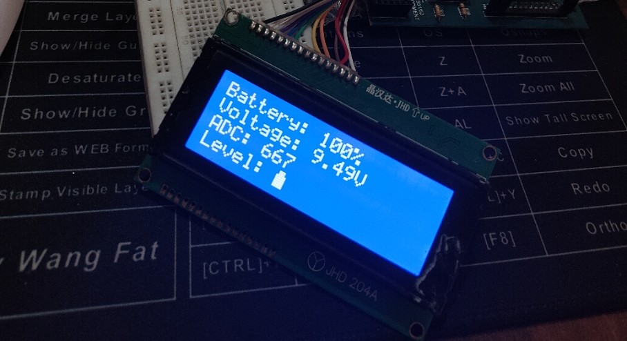
- Observe! You should now see your battery's status displayed clearly on the LCD.
This project provides a robust and visually appealing way to keep an eye on your battery's health. Give it a try, and say goodbye to unexpected power outages in your projects!
Download the arduino INO file here: Github Link
0 $type={blogger}:
Post a Comment